NCC 2022 Volume One - Building Code of Australia Class 2 to 9 buildings
Search the National Construction Code editions
30
Specification 30 Installation of boilers and pressure vesselsThis Specification sets out the requirements for the installation of boilers and pressure vessels in buildings.
To clarify that Specification 30 includes the requirements for the installation of boilers and pressure vessels.
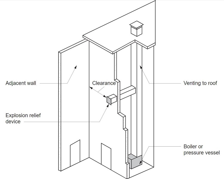
The distance between the vent of any explosion relief device for a boiler or pressure vessel and any adjacent wall, roof, ceiling or other solid construction shall be calculated in accordance with Table S30C2.
| Clearance from | Minimum clearance (metres) |
|---|---|
| Adjacent wall or ceiling/roof |
|
| Two walls at right angles; or one wall and a ceiling/roof |
|
To specify the requirements for boilers and pressure vessels.
S30C2 provides requirements for the distance between the vent of any explosion relief device and any adjacent wall, roof, ceiling or other solid construction. Table S30C2 provides the minimum clearance required which is based on the volume of the space being vented. The minimum clearance is determined by a formula which includes the volume of the space being vented. The intention of the explosion relief provisions are that in the event of an explosion the extent of damage is limited.
The minimum clearance determined in the first row is 0.4 m from an adjacent wall or ceiling/roof.
The minimum clearance determined in the second row is 0.6 m from two walls at right angles, or one wall and a ceiling/roof. This scenario poses a higher risk of damage from overpressure experienced during deflagration, therefore the clearance is increased.
Figure Spec 30
Explosion relief device clearance.
Examples
Examples of compliance with Table S30C2.
V = Volume of space being vented (e.g. furnace to the flue connection)
For this example the volume is 5 m3
x = Clearance from adjacent wall or ceiling/roof
y = Clearance from two walls at right angles; or one wall and a ceiling/roof
Example 1
x = 0.4(V/3)1/3
x = 0.4(5/3)1/3
x = 0.47 m
Therefore the minimum clearance is 0.47 m.
Example 2
y = 0.6(V/3)1/3
y = 0.6(5/3)1/3
y = 0.71 m
Therefore the minimum clearance is 0.71 m.
S30C3 contains two parts. The first is to require the floor surface beneath the boiler or pressure vessel to be water resistant and the floor to be graded away from supports and structural building elements. The second is to ensure that where a safe tray is provided, it must be of a material that is resistant to corrosion from the contents of the boiler.
Building elements surrounding a boiler must be protected from any surface heat by refractory material or effective air spaces so that—
For steel, concrete and timber elements, S30C4 requires the protection of these elements to prevent exposure to certain temperatures emitted by a boiler or pressure equipment.